Standalone iHeater Firmware
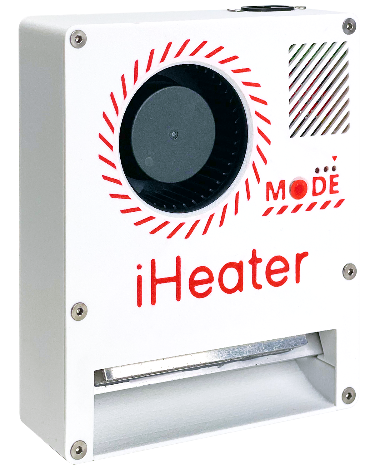
iHeater is a compact and affordable solution for 3D printers without an active heated chamber or with limited connection options to the mainboard. It's especially useful for printers with proprietary boards lacking free ports for fans, heaters, or thermistors. iHeater solves this with a simple and universal approach.
It can operate standalone with its own firmware or be integrated with Klipper over USB.
About the Firmware
iHeater is firmware for a standalone device that manages the temperature of a 3D printer's heated chamber.
Purpose
The device ensures heating and stable temperature maintenance inside the printer's chamber, which is critical for printing ABS, ASA, and other shrinkage-sensitive and adhesion-sensitive filaments.
Power
The iHeater board has no built-in power source. To run it in Standalone mode, supply 5 V to the board.
Make sure the board is powered.
Without power, the LEDs stay off and heating does not start. Check the power supply before looking for the cause in the firmware or settings.
Power options:
- USB cable. Connect USB to a power adapter or any other 5 V source. A host (printer, Klipper) is not required.
- External 5 V supply. Connect the supply to the separate power connector on the board; the connector location depends on the board revision. Use this option when it makes mounting more convenient, for example when powering the board from the printer's power supply.
- 5 V power module on the board (experimental option). The module is soldered directly onto the board and powers it from the selected source. This option is not part of the base kit and has not been tested as thoroughly as the others.
Never connect more than one power source at the same time.
Connecting USB, an external supply, and a power module at the same time causes a power source conflict and malfunctions, and can damage the hardware.
The LED indication shows that the board is powered.
How to Configure the Firmware
File config.h
This file contains all configurable parameters:
| Parameter | Description |
|---|---|
SELECTED_THERMISTOR_TYPE |
Select thermistor type (0-5, see below) |
MODE_TEMP_0-MODE_TEMP_7 |
Setpoint temperatures for each mode. Can be any float value, e.g. MODE_TEMP_4 67.5 |
MAX_TEMP, MIN_TEMP |
Allowed temperature range for the heater |
MAX_AIR_TEMP, MIN_AIR_TEMP |
Allowed temperature range for air |
HEATER_MIN_PWM |
Minimum PWM required to start heater response monitoring |
HEATER_RESPONSE_TIMEOUT_MS |
Timeout for detecting heater response (default 5 seconds) |
AIR_TARGET_TIMEOUT_MS |
Maximum time allowed to reach air target temperature (default 10 minutes) |
TIMER_CLOCK, PWM_FREQUENCY, PWM_STEPS |
PWM configuration (frequency and resolution) |
Thermistors
Selected using SELECTED_THERMISTOR_TYPE:
| ID | Type | Notes |
|---|---|---|
| 0 | ATC Semitec 104GT-2 | Standard used by E3D |
| 1 | ATC Semitec 104NT-4-R025H42G | 104GT alternative |
| 2 | EPCOS 100K B57560G104F | Widely used |
| 3 | Generic 3950 | Default, common Chinese type |
| 4 | SliceEngineering 450 | High-temp support |
| 5 | TDK NTCG104LH104JT1 | Medical-grade accuracy |
Temperature Modes and LEDs
Each mode sets a target temperature and is displayed via binary LEDs:
When entering the mode, the LEDs blink, once the mode is activated, they remain constantly lit.
| Mode | Temperature | LED3 | LED2 | LED1 |
|---|---|---|---|---|
| MODE_TEMP_0 | 0.0°C |  |
|
|
| MODE_TEMP_1 | 55.0°C | |
|
 |
| MODE_TEMP_2 | 60.0°C | |
|
|
| MODE_TEMP_3 | 65.0°C | |
|
|
| MODE_TEMP_4 | 70.0°C | |
|
|
| MODE_TEMP_5 | 75.0°C | |
|
|
| MODE_TEMP_6 | 80.0°C | |
|
|
| MODE_TEMP_7 | 85.0°C | |
|
|
Automatic enabling and disabling r1.1
Macros
These parameters define the activation and deactivation temperatures for the heater, as well as the mode to be enabled upon activation.
Assuming the trigger thermistor is located near the heated bed. With the current settings, the chamber heater will turn on when the bed temperature reaches 45°C and will turn off when the bed temperature drops below 80°C. These parameters are suitable for most filaments that require an actively heated chamber and do not cause logical conflicts during operation.
It is also possible to select the mode that will be activated when the trigger is engaged. For example, TRIGGER_MODE MODE_2 is currently selected, which means that MODE_TEMP_2 will be activated, setting the chamber temperature to 60.0°C.
Working with iHeater-link (r1.1 pulse build)
The iheater_rev1_1_pulse build is designed to pair with the ESP-based iHeater-link module. The module receives commands from the printer, a portal, or a mobile application and forwards the chamber setpoint to iHeater over a single GPIO line. The iHeater firmware is transport-agnostic — it only reads a number: the desired chamber air temperature in °C.
Wiring
- Flash iHeater with the
iheater_rev1_1_pulsebuild (see "How to Flash the Firmware"). - Connect the signal wire from iHeater-link to the TH2 connector on the iHeater board (pin PB1).
- A common GND between the ESP and iHeater is mandatory — use a dedicated ground wire.
- Keep the heater thermistor on its usual TH0 connector. Keep the air thermistor on TH1. Both work exactly as in any other build.
- The trigger connector is not used in this build (its line is repurposed as the digital input).
Never connect or disconnect the signal wire with power applied.
Accepted commands
| Code from iHeater-link | Meaning |
|---|---|
0 |
Heater off |
10 |
Heater off (agreed "off-code") |
45..90 |
Heater on, air setpoint equals the code in °C |
| Any other value | Ignored; previous state is kept |
The minimum 45 °C is defined in config.h as PULSE_MIN_TARGET. The maximum is bounded by MAX_AIR_TEMP (90 °C by default).
LED indication
| State | LED1 | LED2 | LED3 |
|---|---|---|---|
| Waiting for the first frame after boot | chasing light LED1 → LED2 → LED3 with a 1000 ms step | ||
| Link OK, heating off | solid on (link-alive heartbeat) | off | short ~80 ms flash on every accepted frame |
| Link OK, heating on | chasing light LED1 → LED2 → LED3 with a 200 ms step | ||
| Link lost (>5 s with no frame after the first one) | "Beacon": all three LEDs flash together for ~100 ms every 2 s. The heater is off, the fan is on. |
Standard faults (overheat, open thermistor, heater-no-response) work exactly as in analog builds — see "Error Handling".
Link-lost behaviour
The firmware removes heating when commands from iHeater-link stop arriving and resumes operation when they arrive again.
After power-up the firmware waits for the first frame and shows a slow chasing light (1000 ms step). The heater is off. The wait has no time limit: until the link has been established once, the absence of frames is not treated as a link loss.
Once the first frame has been received, the rule is: if no frames arrive for more than 5 seconds, the link is considered lost. During these 5 seconds iHeater keeps executing the last command.
When the link is lost:
- The heater turns off.
- The fan turns on and runs until the link is restored.
- The LEDs show the "beacon": all three LEDs flash for ~100 ms every 2 s.
No error is stored in flash, the MCU does not reset, and there is no need to press the MODE button. When frames arrive again, iHeater executes the received command: with a 45..90 setpoint it resumes heating, with 0 or 10 it stays off.
MODE button
In the pulse build, the MODE button does not cycle modes and does not trigger calibration. Its only purpose is clearing a persisted error at startup. All heating commands come from iHeater-link.
How to Flash the Firmware
Download
Скачайте прошивку со страницы релизов
Using Precompiled Binary
Download the firmware from the releases page
This firmware is pre-configured with the temperature modes from MODE_TEMP_0 to MODE_TEMP_7 (as described above) and designed to work with a Generic 3950 thermistor (type 3 in config.h).
Using DFU Mode (USB)
- Set the BOOT0 jumper
- Connect USB, the device will be recognized as DFU 3.1 Upload the firmware using STM32CubeProgrammer:
3.1.1 Specify the path to the .bin firmware file (e.g.: Firmware/iHeater_v1.2.3.bin) 3.1.2 Set the download address: 0x08000000
3.1.3 Click "Start Programming"
or
3.2 Upload the firmware via command line:
- Remove the jumper and power cycle the device
- Press and hold the BOOT button
- Connect USB, the device will be recognized as DFU
-
Upload the firmware using STM32CubeProgrammer:
3.1.1 Specify the path to the
.binfirmware file (e.g.:Firmware/iHeater_v1.2.3.bin)3.1.2 Set the download address:
0x080000003.1.3 Click "Start Programming"
or
3.2 Upload the firmware via command line:
-
Power cycle the device
How to Use
Before use, make sure the board is powered — see the "Power" section.
- Short press of the MODE button - switches modes (0-7)
- Long press (2+ sec) - resets the mode to 0 (OFF)
- LED indicators display the current mode according to the table above
- Flashing LEDs - mode is active but target temperature not yet reached
- Solid light - target temperature reached
Revision Differences
revision r1.1 features a trigger port for automatic chamber heating control. When a thermistor is connected to the trigger port, heating will turn on and off according to the temperatures specified in config.h, by default 45 and 80 for heating activation and deactivation.
- Short press of the MODE button - switches modes (0-7)
- Long press (2+ sec) - resets the mode to 0 (OFF)
- LED indicators display the current mode according to the table above
- Flashing LEDs - mode is active but target temperature not yet reached
- Solid light - target temperature reached
Error Handling
The device auto-resets and shows an error code using LED indicators. The fan will be switched on at the same time.
| Code | Description | LED3 | LED2 | LED1 |
|---|---|---|---|---|
| 0x01 | Air failed to reach target in time | |
|
 |
| 0x02 | Heater not responding | |
|
|
| 0x03 | Manual shutdown (unused) | |
|
|
| 0x04 | Air thermistor disconnected | |
|
|
| 0x05 | Heater thermistor disconnected | |
|
|
| 0x06 | Heater overtemperature | |
|
|
| 0x07 | Air overtemperature | |
|
|
| 0x08 | iHeater-link lost (pulse build v0.5.0; not stored since v0.5.1) | 0.25 Hz | 0.25 Hz | 0.25 Hz |
| 0xFF | Unknown error |  |
|
|
Resetting an Error
Hold the MODE button during startup until the LEDs change. The stored error will be cleared from flash memory, and the device will resume normal operation.
Fine Tuning
If there is confirmation that the thermistor readings deviate from the actual temperature, the fine tuning function can be used. For this purpose, it is necessary to measure the resistance of the corresponding resistors and record these values instead of the default ones.
#define PULLUP_TH0 4700.0f
#define PULLUP_TH1 4700.0f
#define PULLUP_TH2 4700.0f
This software is licensed under the GNU GPL version 3 or later. Commercial use is permitted. See the LICENSE file for details.