iHeater Link — quick guide
iHeater Link is a connectivity module for the iHeater controller with firmware iheater_revХ_Х_pulse. It is an ESP32-C3 / ESP32-S3 board that:
- Connects to Wi-Fi and links iHeater to portal.idryer.org.
- Receives chamber target temperature from the printer through Moonraker (Klipper), Bambu Lab (LAN), or Home Assistant integrations.
- Converts the target into a pulse signal and forwards it to the iHeater controller over a single GPIO.
iHeater is controlled "over the wire": one signal pin on the ESP feeds the iHeater signal input. Wi-Fi and integrations are Link's job; heating and safety are iHeater's job.
The single-wire link does not constrain where Link is placed. The ESP board can be installed outside the heat chamber. This avoids:
- chip and peripheral overheating when the chamber runs at 60+ °C;
- thermal lock-ups of the radio section and Wi-Fi session drops during long heating cycles;
- accelerated component degradation.
Only the iHeater controller — designed for high-temperature operation — stays inside the chamber. Signal-wire length to the ESP is limited only by reasonable line load (tens of centimetres — no concerns).
Supported boards
| Board | |
|---|---|
| ESP32-C3 Super Mini | ✅ |
| ESP32-C3 DevKitM-1 | ✅ |
| Seeed XIAO ESP32-S3 | ✅ |
| Waveshare ESP32-S3-Zero | ✅ |
Any other ESP32-C3 or ESP32-S3 board can be used as long as a free GPIO is available for the signal output. Check the manufacturer's pinout.
Wiring
Never connect or disconnect wires while power is applied.
Power goes to the ESP through USB-C. The ESP, in turn, powers the iHeater controller over the 5 V line. This is the simplest setup. If needed, iHeater power can be sourced separately — Link does not depend on the power scheme.
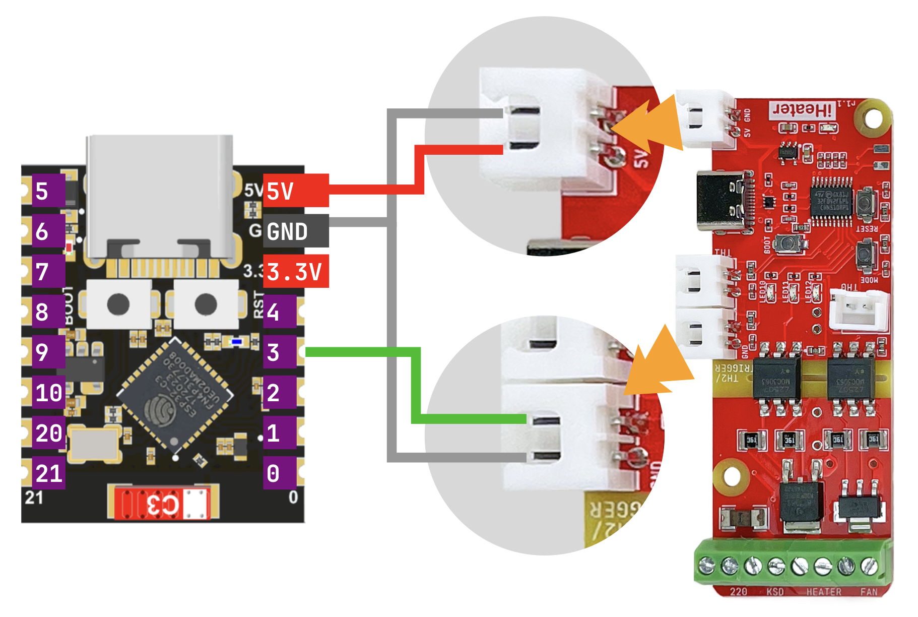
Connections (same for all supported boards):
| ESP | iHeater | Purpose |
|---|---|---|
5V |
5V |
controller power |
GND |
GND |
common ground |
GPIO3 |
signal input | pulse setpoint |
Board pinouts
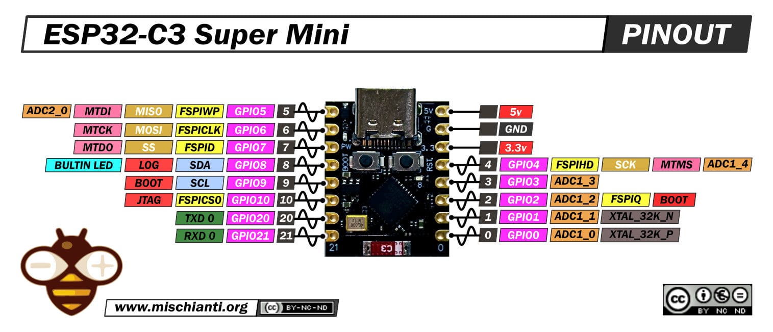
ESP32-C3 Super Mini:
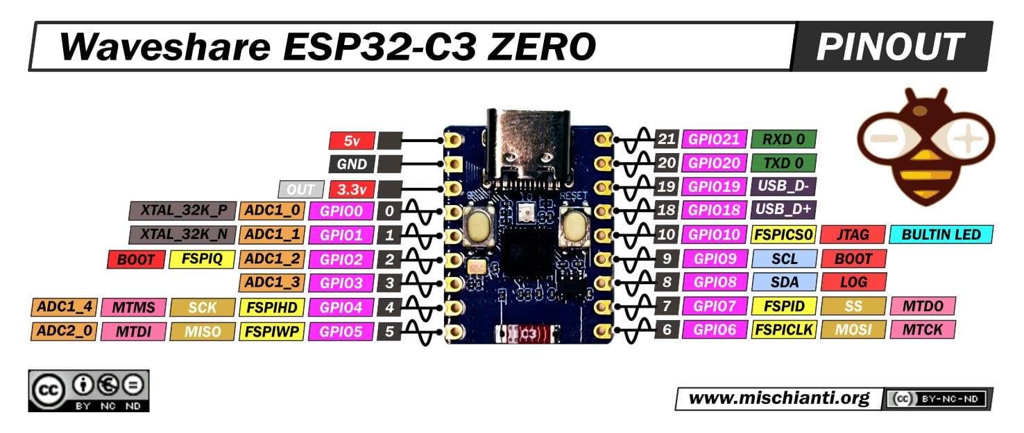
Waveshare ESP32-S3-Zero:
Flashing via the web flasher
The web flasher is hosted at install.idryer.org.
- Connect Link to a USB port on the computer.
- Open install.idryer.org and select the iHeater Link device.
- Select the board variant.
- Click Connect and pick the serial port (typically
USB JTAG/serialorCH340). If the device is not detected, holdBOOTon the board and briefly pressRST. - Click Install. The flasher writes the firmware.
- When flashing completes, the Wi-Fi setup wizard opens.
Wi-Fi setup
After flashing, the Improv wizard opens automatically over the serial port.
- Enter the SSID and password of your 2.4 GHz network.
- Wait for the Connected status. The Link status LED switches to a slow blue "breathing" pattern.
If the wizard does not open, unplug USB and reconnect via Connect without re-flashing.
ESP32 supports 2.4 GHz only. 5 GHz networks will not work.
Pairing with the portal
- On the flasher page click Connect and Claim.
- The device receives the
START_CLAIMcommand. After a few seconds a PIN is shown on the page. The PIN is valid for ~5 minutes. - Open portal.idryer.org → Add device → enter the PIN.
- Once paired, the device appears online in the list.
If the response is CLAIM_ALREADY:DEVICE_…, the device is already
paired to this or another account. Remove the device from the portal,
then repeat the pairing.
Connecting to iHeater
- Power the controller off.
- Wire ESP to iHeater per the diagram above:
5V,GND,GPIO3→ iHeater signal input. - Apply power to the ESP via USB. The controller is powered through the 5 V line.
On boot, Link connects to the portal, activates the selected integration, and starts forwarding the chamber target to iHeater.
What you should see
- LED 1 stays on, LED 3 blinks once per second — Link-to-iHeater communication is established.
- When the link is lost, all LEDs blink at 1 Hz.
- All other errors are unrelated to Link and follow the standalone firmware indication.
Diagnostics
The device menu has a DIAGNOSTICS → DIAG LOG entry. When enabled, the serial port outputs a detailed report once per second: Wi-Fi status, MQTT status, active integration, current target, connector errors.
Full diagnostics reference is available in the idryer-core library documentation in the project repository on GitHub.